Hey readers!
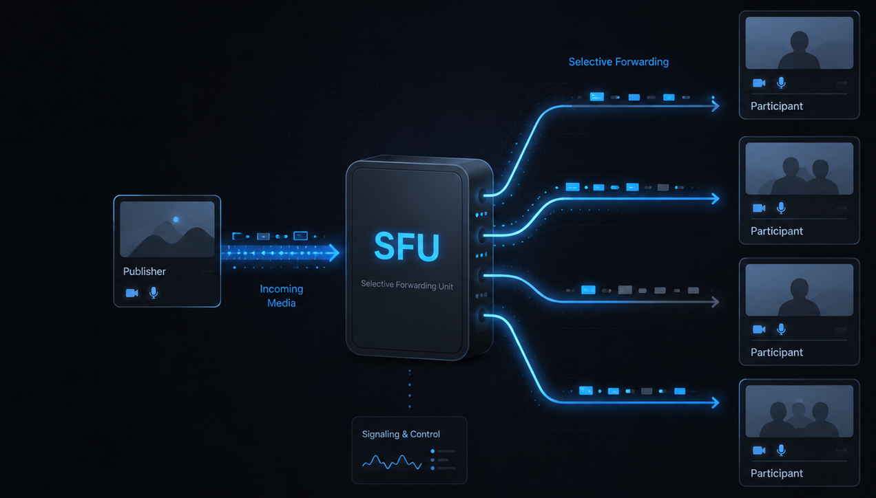
I've built a minimal SFU (Selective Forwarding Unit) media server in Go using pion/webrtc.
My interest in real-time communications started about a year ago. Debugging a third-party WebRTC integration at work made me curious about what was happening underneath. Since then I've been learning this space alongside my job, filling gaps in networking fundamentals and building progressively more complex projects.
I'd previously built a media server using mediasoup, but this time I wanted to go below its abstractions - work at the protocol level, with primitives, and understand the decisions that production SFUs make.
LiveKit was a major influence. I chose Go specifically because of its ecosystem in this space, and set out to build a scaled-down replica to learn how it works internally.
This post is an architectural overview of what I've built - the components, their responsibilities, and how they interact. Deeper implementation posts (simulcast layer switching, concurrency model, resource cleanup) will follow separately.
Disclaimer: This is a self-learning project. The architecture reflects my current understanding and may differ from industry implementations. Where I'm aware of the gap, I call it out.
Project Roadmap
I broke the learning path into self-contained projects, each with its own definition of done, building up from raw networking to the SFU.
- Project 0 - UDP echo server and TCP multi-client chat server (raw sockets, no WebRTC)
- Project 1 - STUN client from scratch (manual parsing of the binding response to extract public IP and port)
- Project 2 - WebSocket signaling server (SDP and ICE candidate exchange between peers)
- Project 3 - Peer-to-peer video call using browser-native WebRTC APIs (no media server)
- Project 4 - Minimal SFU using pion/webrtc (3+ peers forwarding media through the server)
- Project 5 - Telemetry pipeline (jitter, bitrate, packet loss, per peer and per room)
- Project 6 - Horizontal scaling (multi-node SFU with room-to-pod routing)
Projects 0 through 4 are complete. This article covers Project 4.
Architecture Overview
In this section I'll walk through the high-level architecture of the SFU. The project is divided into conceptual layers, keeping separation of concerns in mind. A few abstractions (Go structs) are also established to encapsulate internal behaviour from outer usage.
But let's first talk about what the SFU actually does.
- Manages rooms and owns the peers inside them
- Handles audio and video tracks per peer
- Forwards each peer's tracks to the other peers in the same room
- Handles publishing of simulcast layers from the publisher, and switching to a specific quality layer for subscribers
- Sends metrics like bitrate, packets per second, and frames per second, per participant track
Here's how the layers fit together. Each layer owns a specific concern, and the dependency only flows one way - the Room and Peer reach into media primitives, but the media layer knows nothing about the Room or Peer.
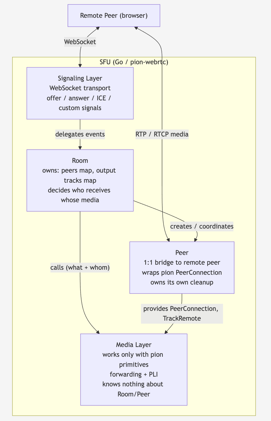
Components of the SFU
Signaling Layer
Though it's not part of the WebRTC spec, the signaling plane serves two purposes for the SFU and a remote peer.
- Sharing offer/answer and ICE candidates before any RTP packets start flowing between them (and again on renegotiations)
- Acting as a general data channel between the peer and the SFU. This traffic may be related to the meeting but not necessarily WebRTC-specific, like pushing room stats from the SFU to each peer, or sending custom signals from a peer to the SFU.
The signaling plane is handled by a WebSocket connection, which registers all the necessary handlers for incoming messages. WebSockets seem to be an industry standard here because they maintain a low-latency, bidirectional channel between the SFU and its peers.
The signaling plane interacts with the Room component to register room-related callbacks and to delegate the handling of certain events to the room layer, which manages those events internally.
Room Component
How does the SFU keep track of which remote peers belong to the same meeting? There has to be a concept of grouping that tracks the whole lifecycle of the peers within it. In this SFU, that grouping is conceptualised as a Room.
A Room owns two important things: a map of its peers keyed by peer ID, and a map of all available media tracks from earlier-joined peers, which are subscribable by any late joiner.
A Room does not own any peer-level behaviour, nor does it own any media forwarding logic, because that is what the media plane owns. The Room just decides whose track is forwarded to whom. The mechanism is managed by the media layer.
The signaling layer never reaches past the Room to touch a peer connection directly. It hands the Room an event ("this peer joined", "this message arrived") and lets the Room coordinate the rest. This keeps the transport concern (WebSockets) separate from the room-state concern.
Peer Abstraction
The Room knows which peers are in it and what tracks they've published, but so far nothing on the SFU actually represents a remote peer. That's what the Peer abstraction is for.
A Peer on the SFU side is a near one-to-one representation of the actual remote participant, built around a pion PeerConnection. Think of it as a two-way bridge: media and events flow in from the remote peer, and the SFU pushes other participants' media and messages back out across the same bridge.
We handle traffic on this bridge by registering callbacks for the events we care about - a track being published, an ICE candidate arriving, the connection state changing. For example, when the remote peer publishes a track, our handler adds that track to the Room's track map and kicks off forwarding it to the other peers. (The forwarding itself lives in the media plane; the Room just decides it should happen.)
A Peer is also responsible for cleaning up its own spawned resources when it leaves. The Room doesn't manage a peer's teardown - the peer owns its own lifecycle.
Media Layer
The Room manages the grouping of peers. The Peer represents the two-way bridge between the actual remote peer and the SFU. So which part of the SFU actually does the magic that lets a remote peer see and hear the others in the room? That's the media layer.
This layer doesn't know anything about the Peer or Room abstraction. It works primarily with pion/webrtc primitives like PeerConnection, TrackRemote, and TrackLocalStaticRTP, and does the media forwarding from source to destination. The how of forwarding is managed by this plane, whereas the whom (peer IDs) and the what (source and destination tracks) are provided by the Room.
The most important responsibility of this plane is to forward media - audio and video, whether forward-only or simulcast quality tracks - from the publishing peer to the other remote peers.
This is supported by a sub-responsibility: sending periodic PLI (Picture Loss Indication) requests to the publishing peer via that peer's PeerConnection (the pion/webrtc primitive, not the Peer abstraction). This ensures the SFU regularly gets a fresh keyframe, which avoids frozen, green, or pixelated video for newly joined peers.
The actual forwarding logic for forward-only and simulcast peers will be explained in the next (How) part of this series.
How the Layers Interact
The static picture above shows the boundaries. The more interesting question is what happens at runtime. Two flows capture most of it: a peer joining a room, and a peer's track reaching everyone else.
Join flow
When a peer joins, the signaling layer takes the WebSocket message and delegates to the Room. The Room gets or creates the room, creates the Peer (and its underlying PeerConnection), registers the event callbacks, and subscribes the new peer to the tracks that already exist. The peer then sends its own offer, which covers those existing subscriptions in one negotiation.
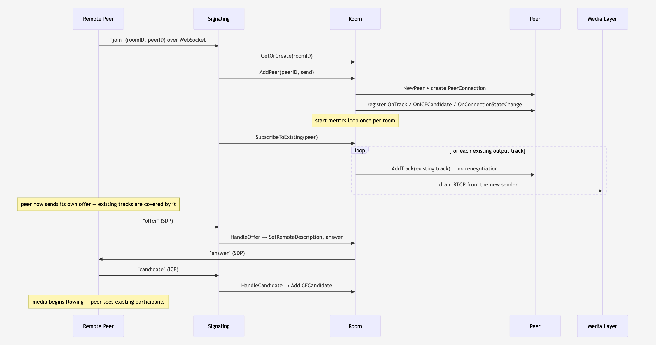
The takeaway is the handoff chain. Signaling never touches media or peer connections directly - it hands events to the Room, and the Room coordinates everything else.
Publish and forward flow
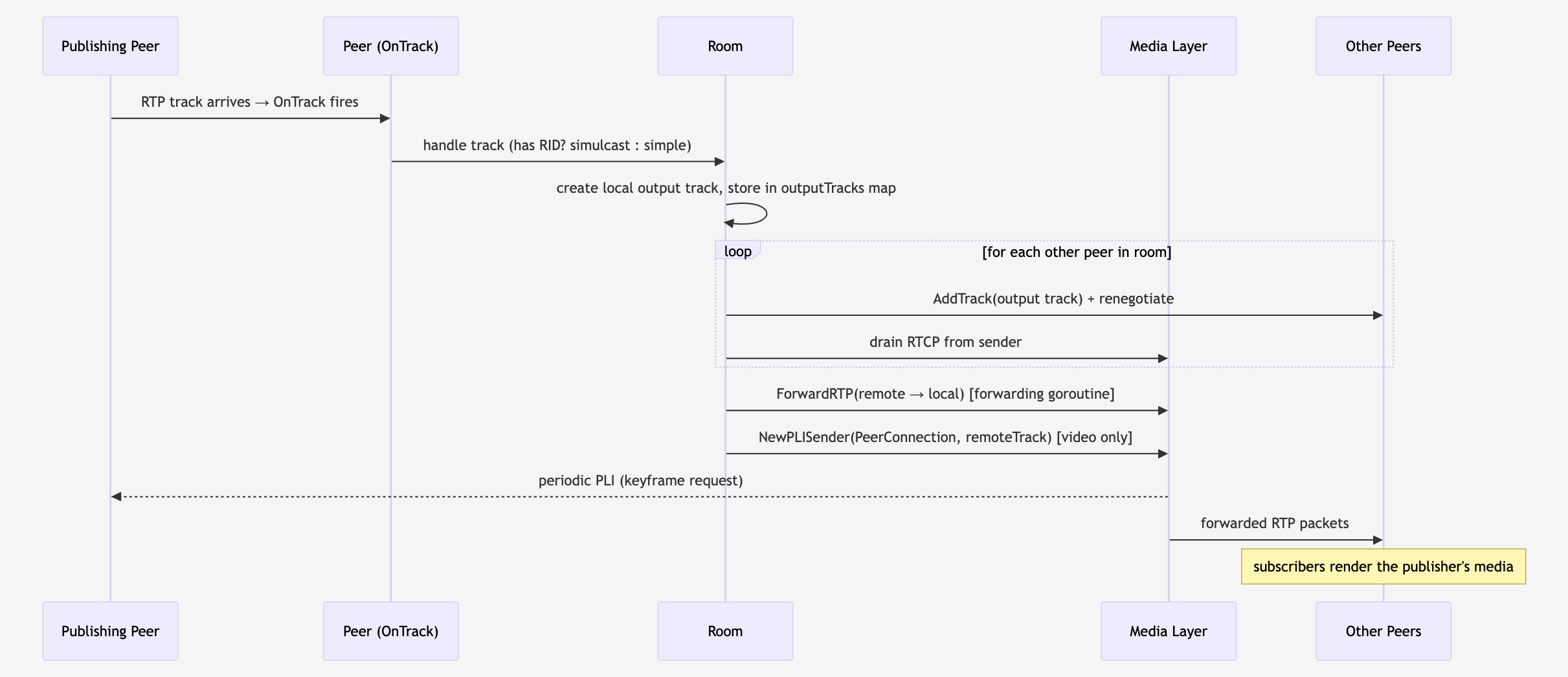
When a peer publishes a track, its OnTrack callback fires. The Room decides whether the track is a simple forward-only track or a simulcast track, registers a corresponding output track, and subscribes the other peers to it. From there the media layer takes over: it forwards the RTP packets and, for video, starts sending PLI requests to the publisher.
Coming next
Part 2 (How) will cover the internals: the forwarding loop, simulcast layer switching, sequence-number and timestamp rewriting, and the PLI mechanics. Part 3 will cover the concurrency and lifecycle side - goroutines, mutexes, and how resources get cleaned up when a peer leaves.
Thanks for reading. If you're working in real-time communications, or just curious about this space, I'd love to connect and hear your thoughts. Feel free to reach out on LinkedIn.